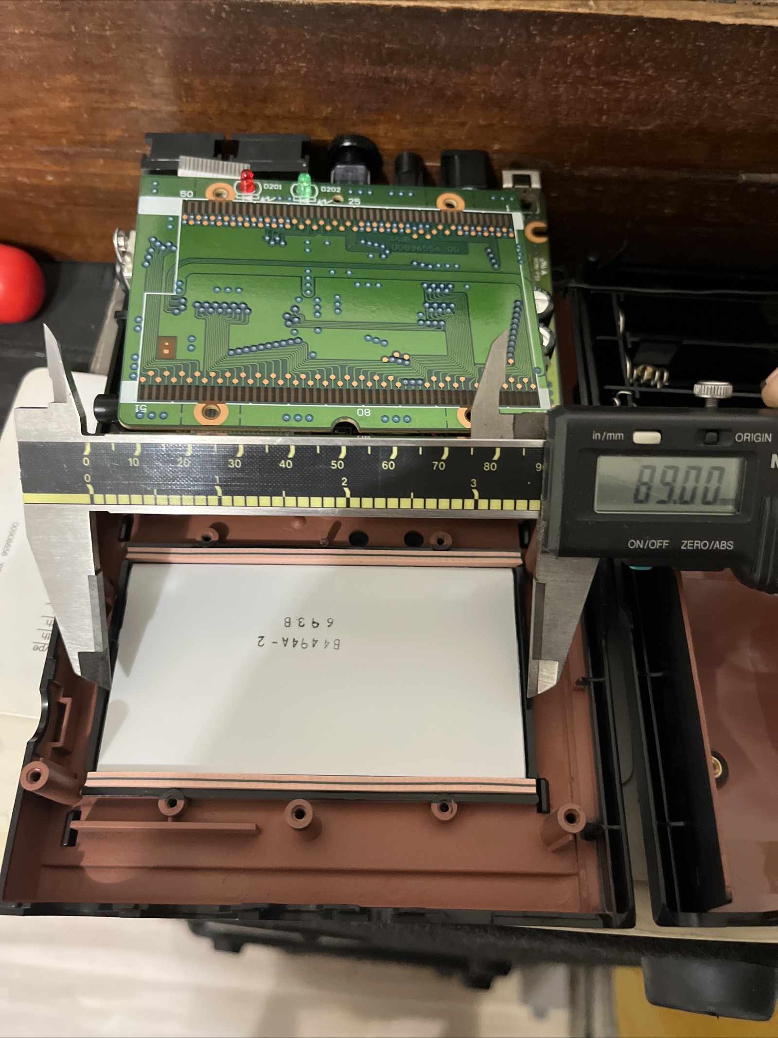
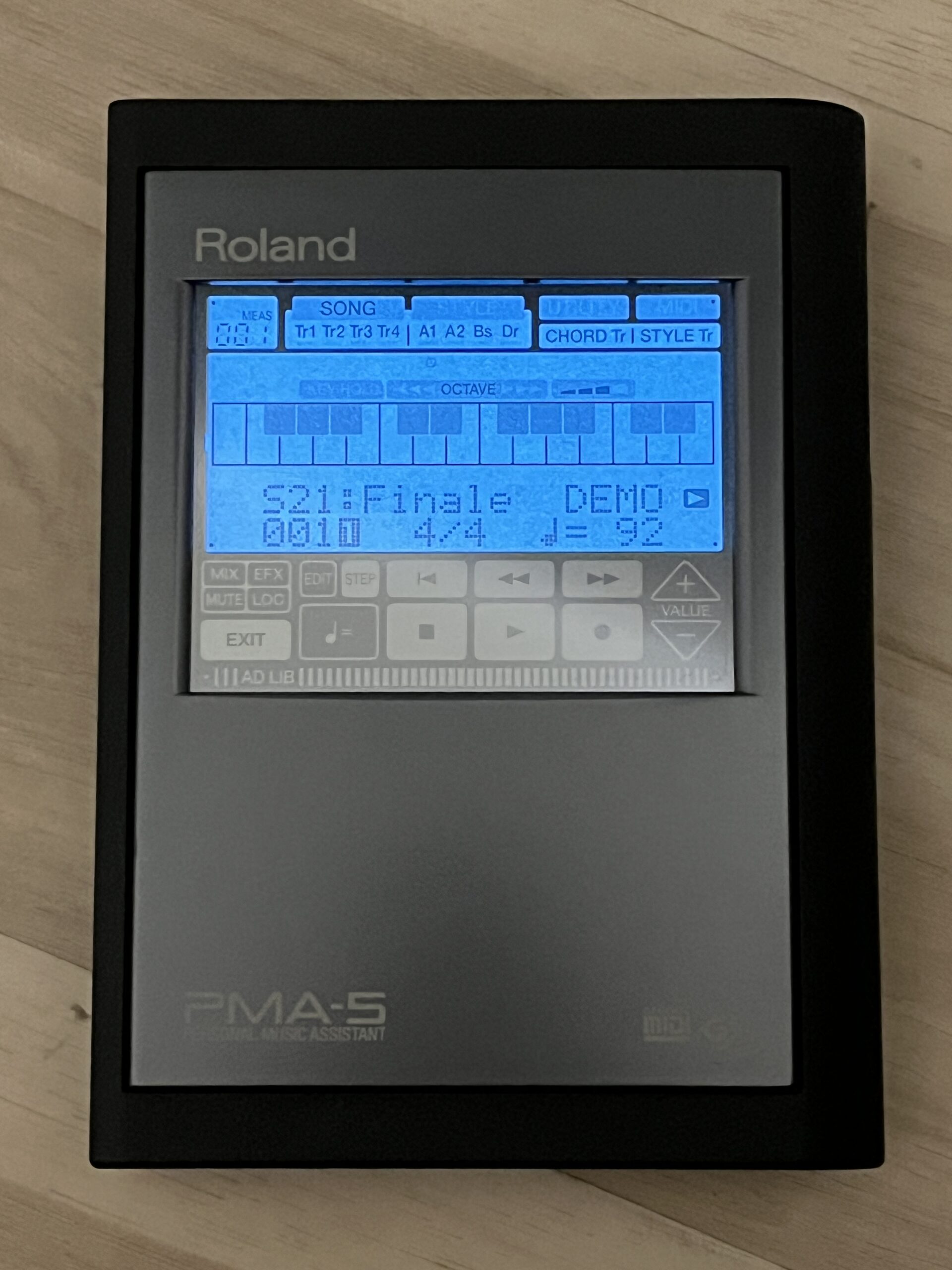
This is a backlight mod for the Roland PMA-5. It has been tested and really looks awesome. I had to work through issues such as, dimension constraints, power variances and transformer noise. LED backlights are too thick for this application. An EL panel, DC/AC transformer, buck converter & dc power filter was used. Except removing the LCD mirror, original shell and unit operation was left unmodified. The EL transformer operates between 1-4VDC and the unit power is 9VDC.
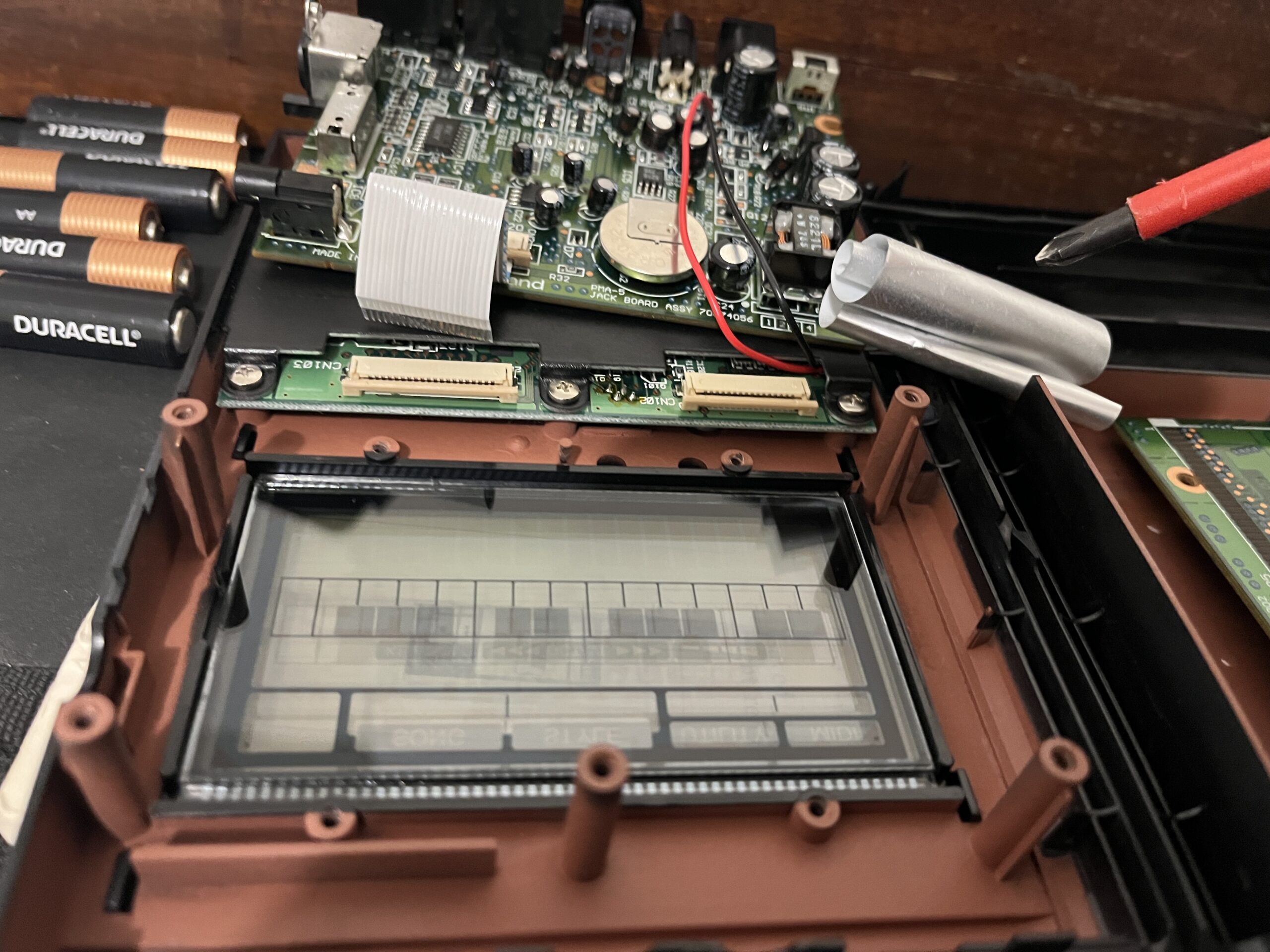
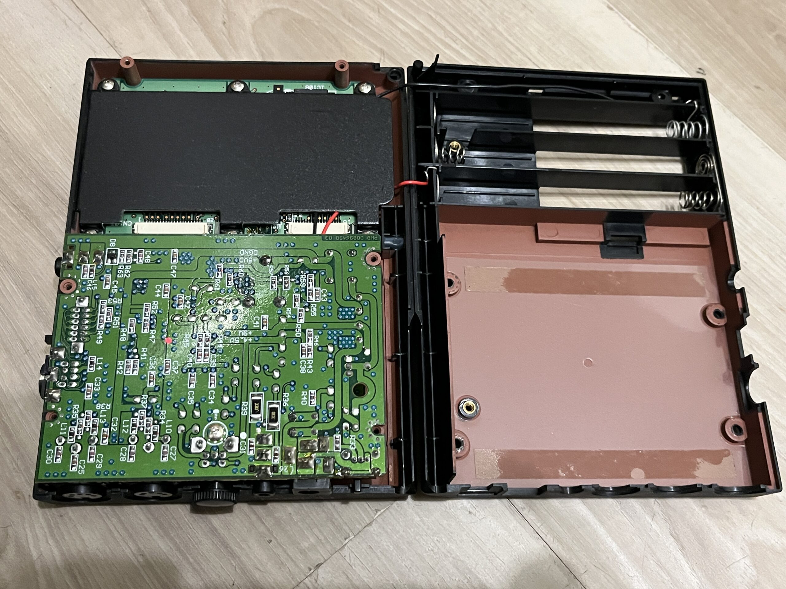
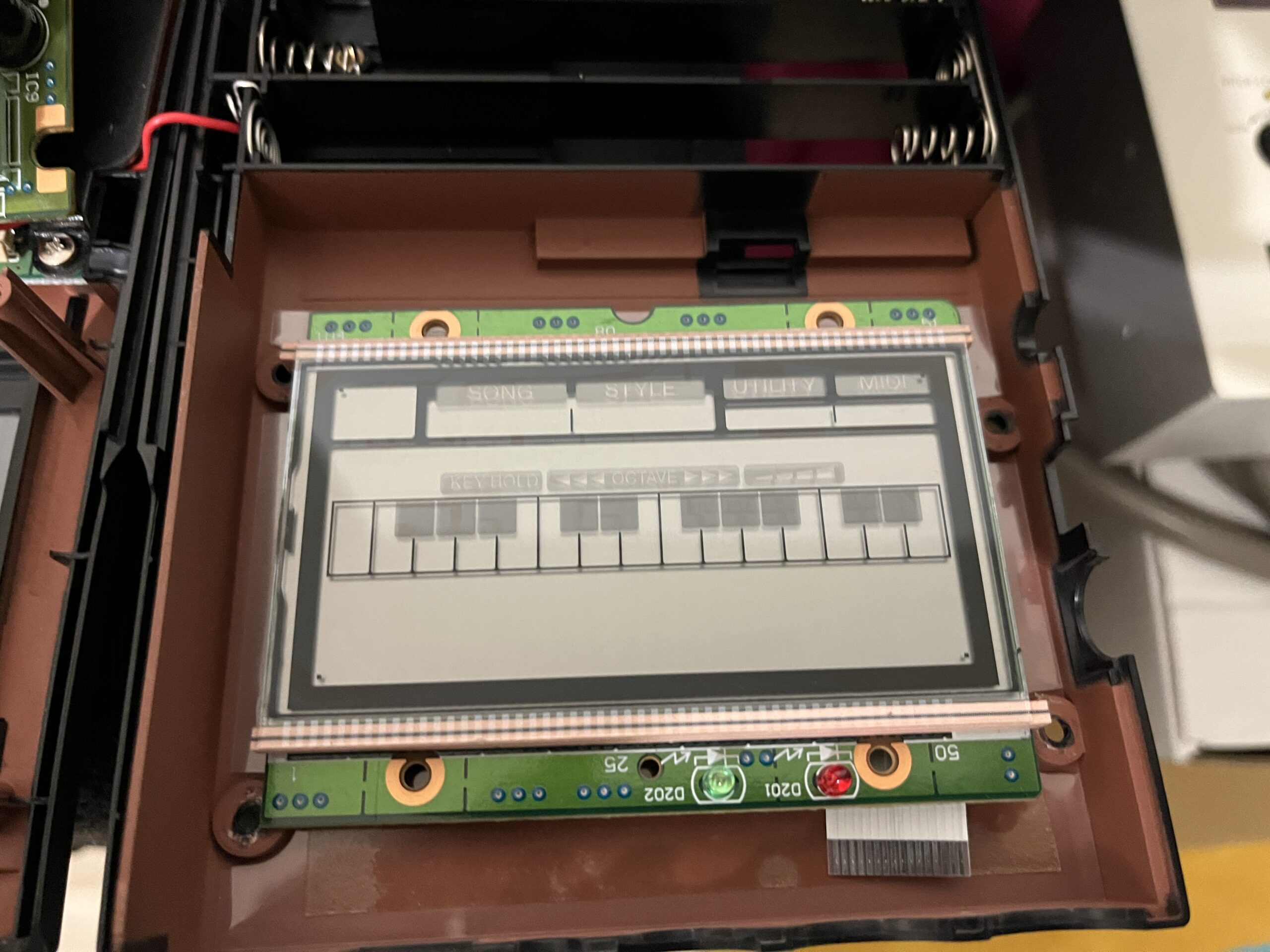
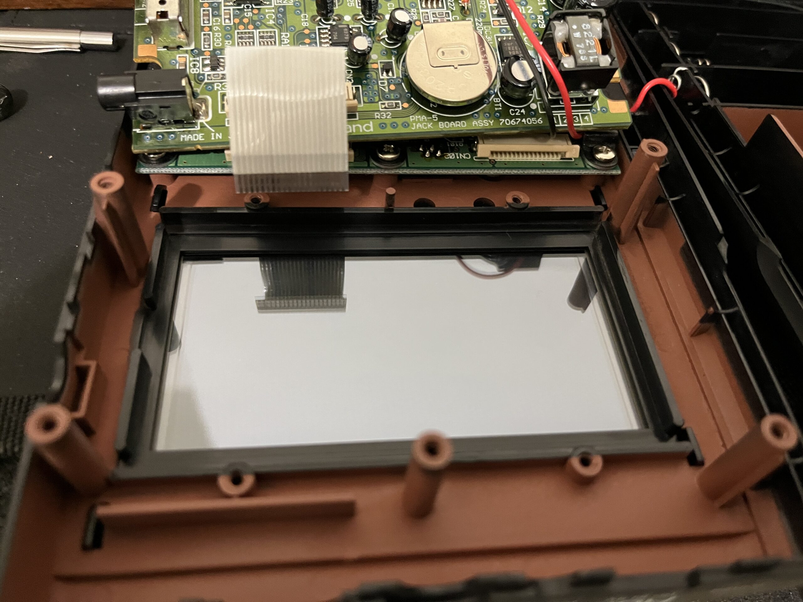
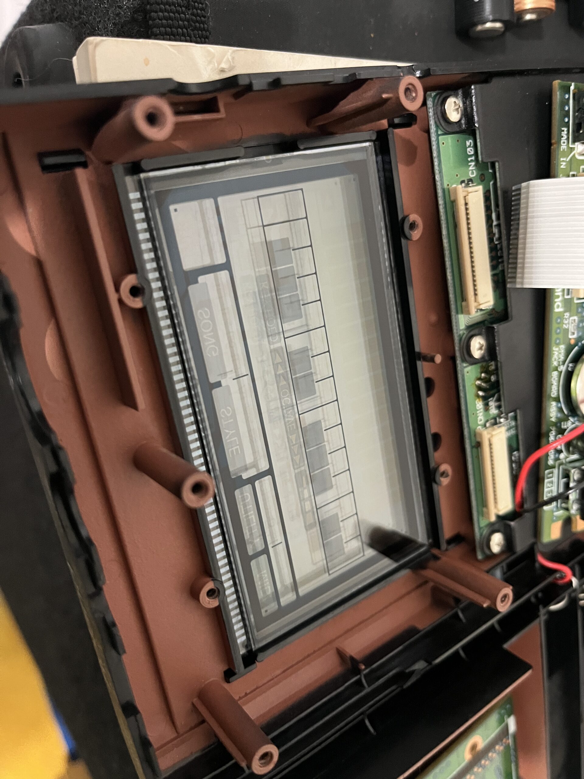
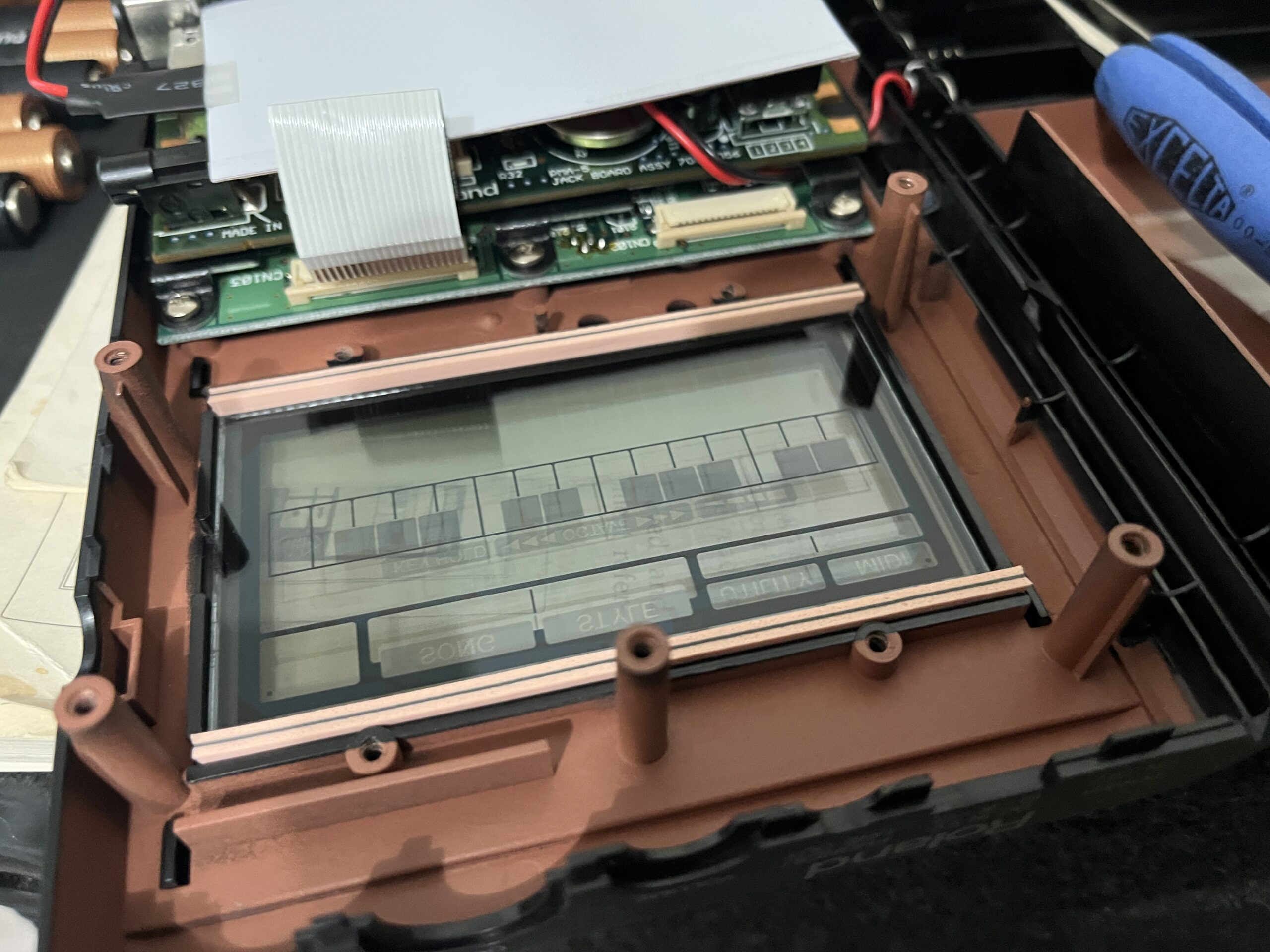
First obtain an operational unit. Tear down the unit to access the LCD screen. The rubber contacts probably will be stuck to the assembly. Carefully peel apart the assembly and remove the mirror sticker on the back of the LCD screen. Clean the screen from sticker residue with IPA. Clean all the rubber contacts, glass contacts and PCB contacts gently with IPA and a cotton swab. Remove any dust or debris.

Next you will need these parts.
EL Panel and Transformer
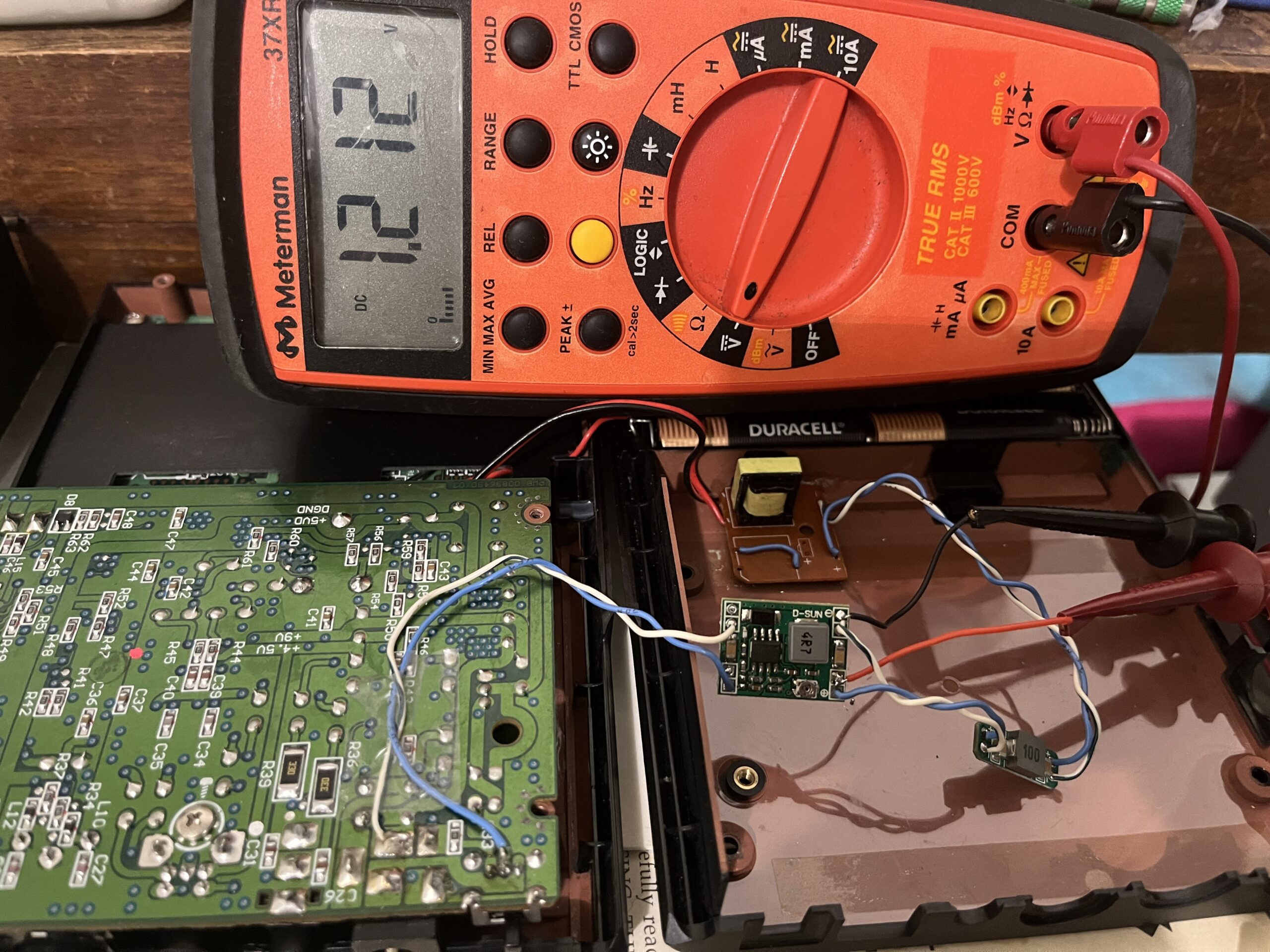
DC Buck Converter
DC Power Filter
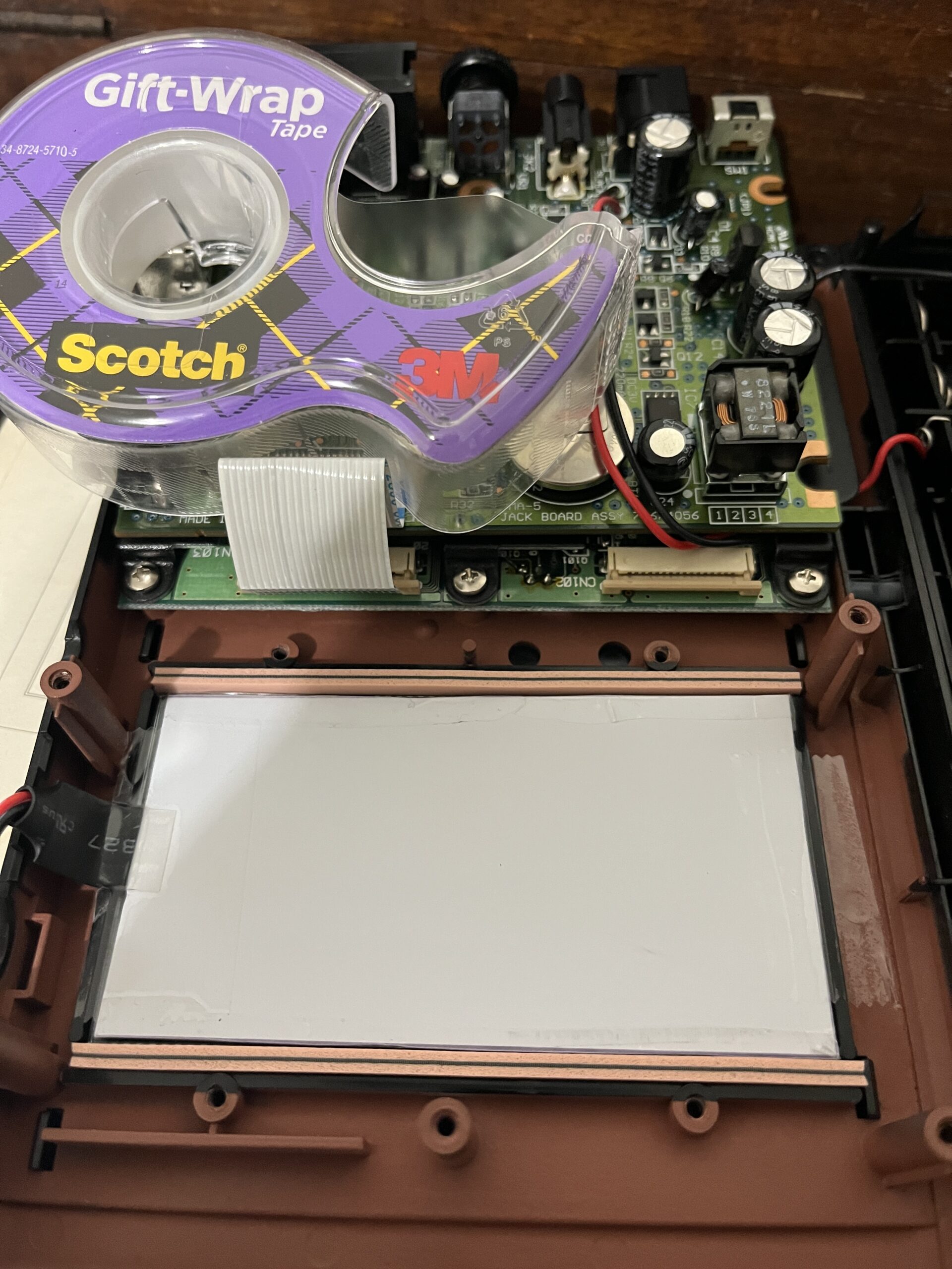
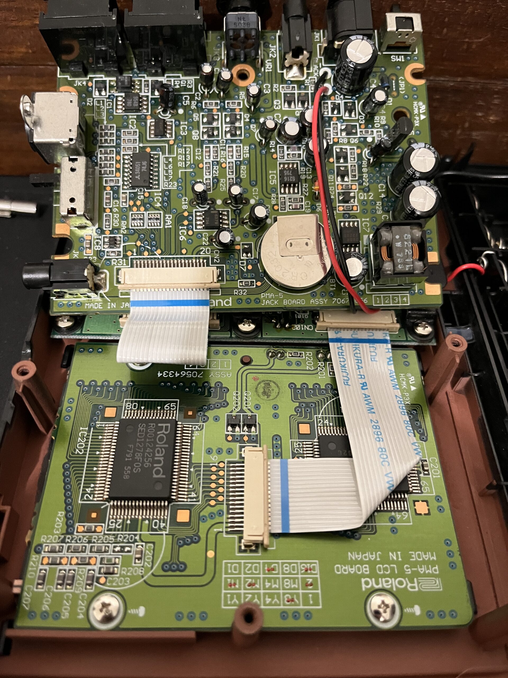
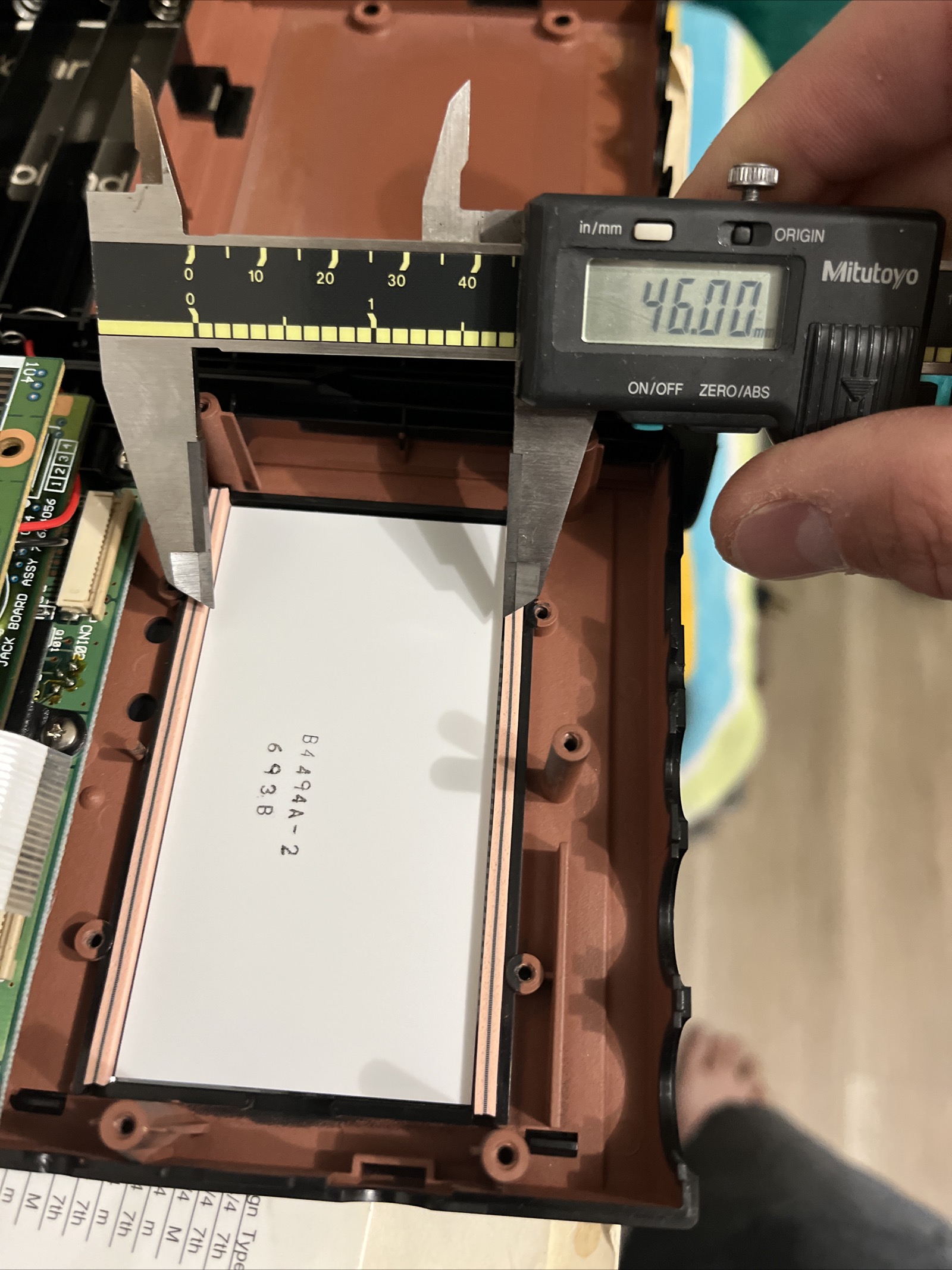
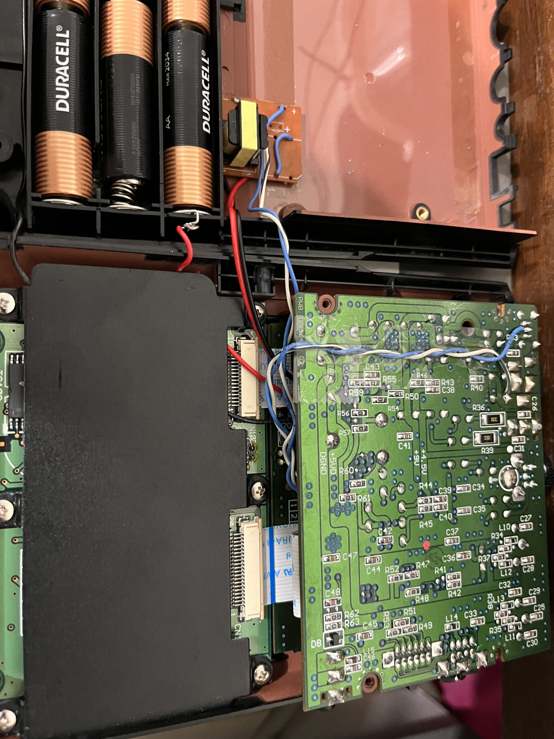
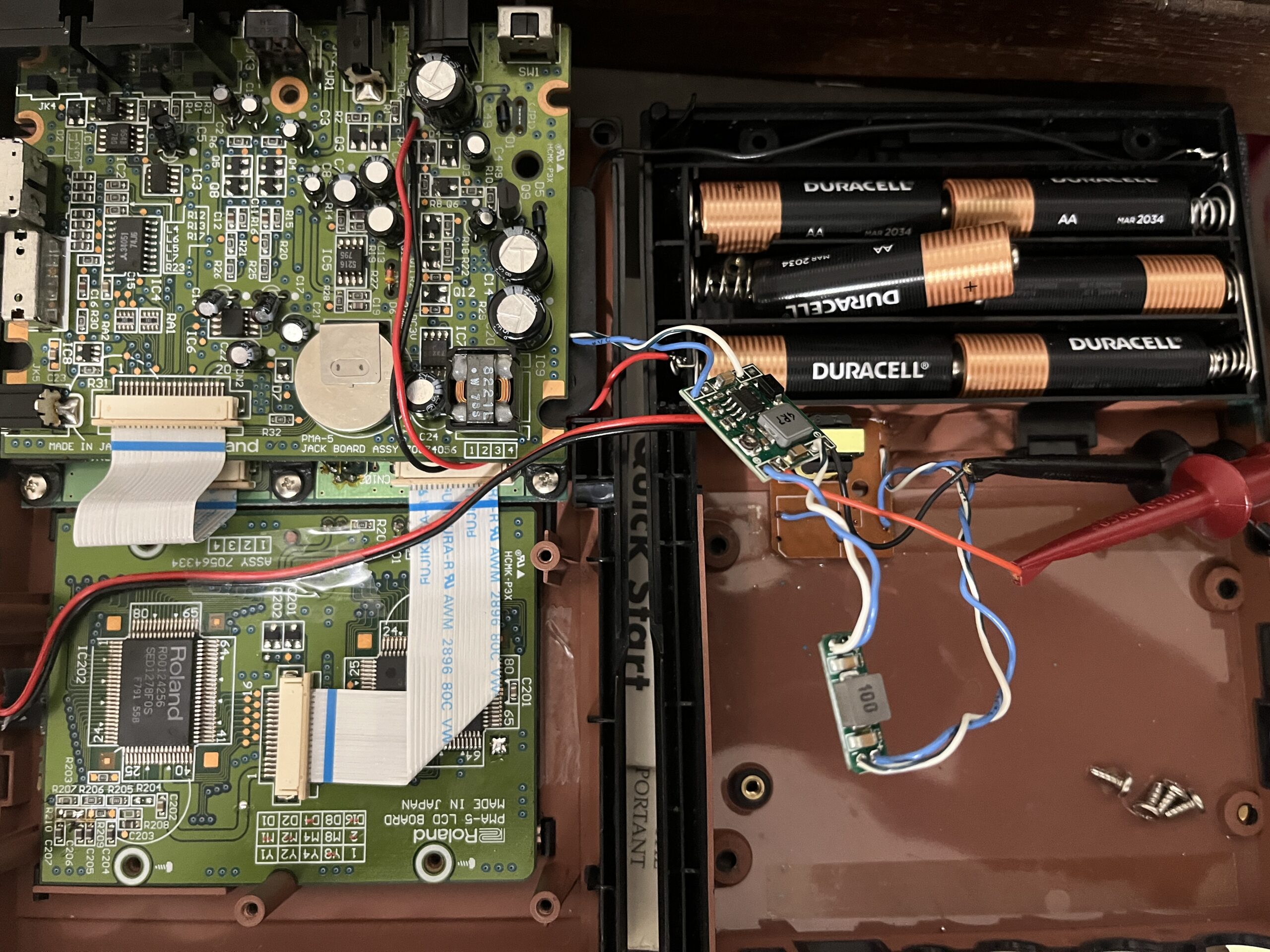
The El panel should be cut to size and then the sides taped. I dismantled the EL transformer box and de-soldered the switch and led from the unit. A wire jumper was used in place of the switch so that it turns on when the unit is switched on. I then found that the optimal DC output of the buck converter should be at 2VDC. The transformer should be mounted in the exact location as the photo posted. I used tape to cover the electronics and placed then between the main PCB boards of the unit. Noise to the headphone output will occur if you route the EL AC wire across CPU chip on the board. Tape this wire to the board above the chip, do not cross this line over chips.
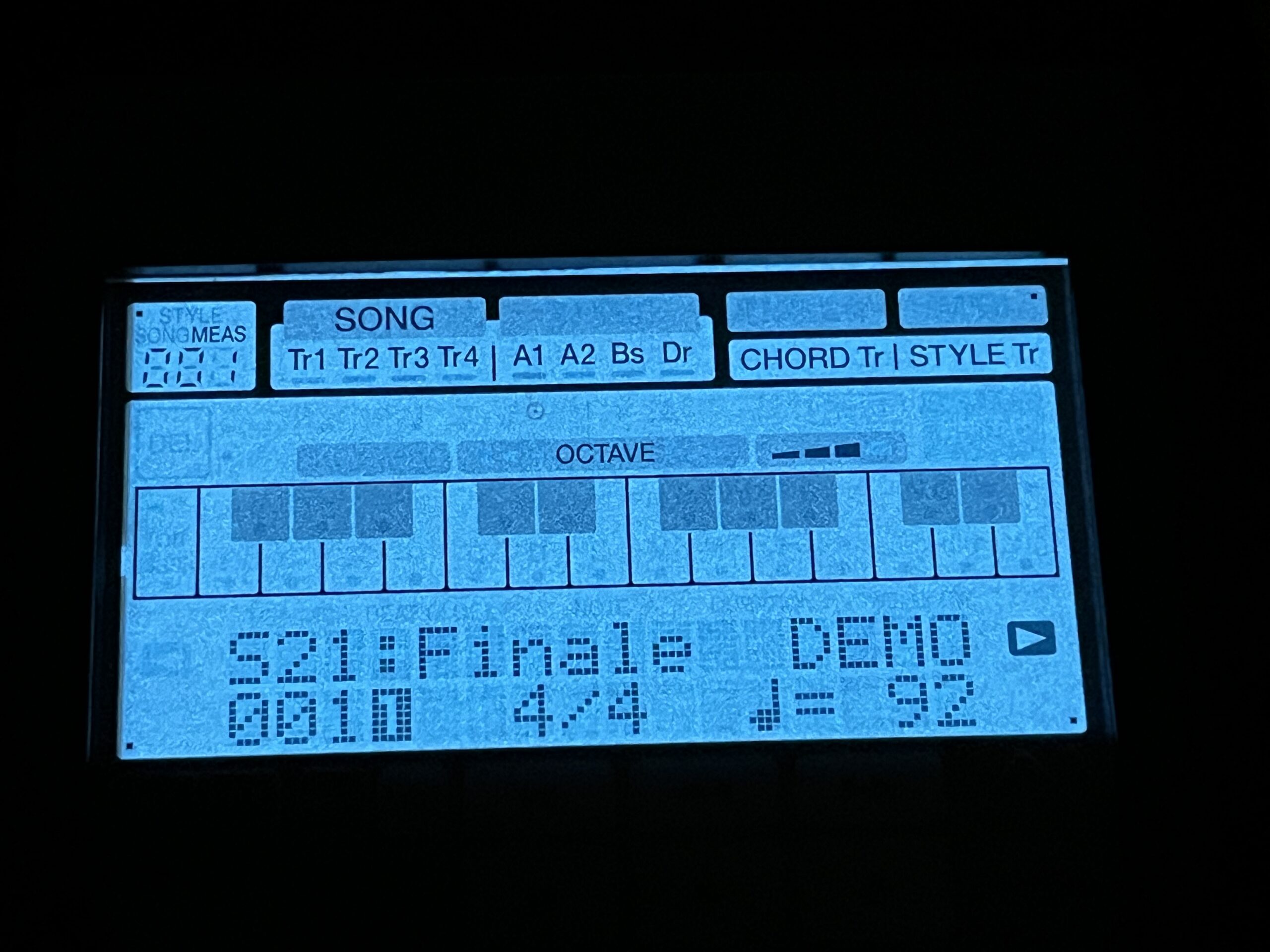
Regarding Dim Display:
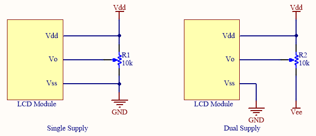
The device was set to have a 45 degree viewing angle with either a fixed resistor or controller. If your display is dim try angling the display to view it better. I can not locate the schematics for this unit, without this it is very difficult to locate the pins for Vdd, Vo, & Vss or the fixed resistor. With this information I could add potentiometer to adjust the viewing angle by controlling the Voltage to the LCD.